|
The PELCO® Dimpler™ is the latest model in the evolution of the Dimpler line formerly available from South Bay Technology and provides Automated Precision Thinning of Specimens for TEM Analysis, for deprocessing and failure analysis, and similar applications where targeted fine polishing is required. It is a precision electro-mechanical metallographic lapping instrument that will continuously monitor and control dimpling parameters and accurately terminate at a preset specimen thickness. This electronic and mechanical integration has added repeatability and reliability to the dimpling process, as well as automation.
Active monitoring of the Z-position, feedback-controlled damping, and automated controls for determining termination of processing work together to provide repeatable, reliable results in sample preparation.
Z Position
The Z position is continuously monitored via a non-contact sensor. The digital display indicates the dimple depth in microns, and is updated once every revolution This negates any errors due to tool run out, especially significant when using padded polishing tools. The termination depth can be set using the Z-position, allowing processing to stop when a specified depth of material is removed.
Termination
Process termination can be determined using the built-in timer, or by the Z Position. When using Z Position termination, the timer counts up to measure the total time elapsed until the Z Position is reached. This is useful for creating process recipes for various sample types. Four factors improve the overall stability during processing, and the termination accuracy:
- Non-Contact Position Sensor
- Tool Phase Sensor
- No external measuring device
- Magnetically coupled arm damping
The Non-Contact Position Sensor measures the location of the fulcrum arm which corresponds precisely to the thickness of the specimen. This sensor has an accuracy of better than one micron. Since it is non-contacting there are no detrimental effects on the action of the fulcrum arm. The reaction time of the sensor is fast enough to terminate the dimpling process the first time the Tool Phase Sensor indicates that the Z termination set point has been reached. Specimen thickness is measured directly on the PELCO® Dimpler™ with the tool surface as the measuring point. The dimple depth and the Z termination set point are measured with the same reference. This prevents any measurement error from being translated directly to a termination error.
Damping
Damping of the arm is accomplished by using position information from the Non-Contact Position Sensor, processing it and feeding it back to the arm motor, which controls the up/down force of the arm. The position sensor and the processing circuit is fast enough to actively dampen any vibration the arm may experience. Since the damping force is magnetically coupled to the arm there is no mechanical play in the system, allowing damping response on the sub-micrometer level. Damping is adjustable from zero
damping to stiff damping.
Damping offers three significant attributes:
- Vibrations that can crack thin specimens
are greatly reduced.
- Keeps tools round, negating excess impacts,
providing more accurate Z position control.
- Tool gently contacts the specimen when the
arm is lowered.
Automated Controls
Automated features make the dimpling process more repeatable and easy to use. Tools are raised and lowered at the touch of a button; dimpling force, damping force, fine balance, and Z offset (termination point) all are set from the front panel.
Once dimpling has begun no monitoring is necessary. After the initial specimen thickness has been measured, the specimen is mounted and the user simply selects a dimple depth and begins dimpling. The precise Z position of the tool/surface interface is continuously displayed while dimpling with any tool. When the selected dimple depth is reached the PELCO® Dimpler™ controls will automatically raise the arm then stop the tool rotation, specimen rotation, and clock timer.
Working Interface
The working interface for the unpadded tools shows very high stability in terms of the ΔZ reading (change in the offset value), with any deviation usually the result of tilt in the mounted sample. Research has indicated that for padded tools, the working diameter is within the nap of the pad. In this case, the ΔZ between the working interface and the specimen is a function of dimpling load (force setpoint), tool speed, damping, and pad compliance. After the dimpling load, tool speed, and damping are selected, the working diameter will stabilize at the working interface of the pad. This working interface is monitored on the Z display and used as a reference location from which a specimen is to be dimpled further.
Specimen Mounting
Different mounts are available depending on the size and type of sample. TEM specimens are generally mounted on optically smooth sapphire flats. The low thermal mass of the flat reduces mounting and dismounting times and the smooth surface allows the dimpled specimens to be easily removed. The hardness of sapphire limits damage if specimens are accidentally perforated due to operator error. The retainer ring which secures the sapphire flat also serves as a slurry reservoir. This platen set is used with the traditional Dimpler tools. For larger specmens for surface analysis or delayering a separate, shorter magnetic base and platen set is used with larger diameter tools. These were developed for delayering and deprocessing.
Tools
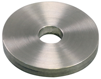
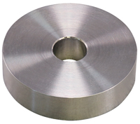
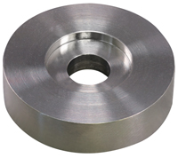
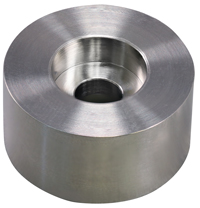
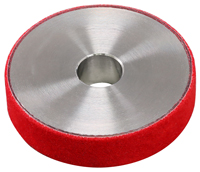
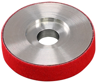
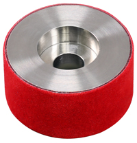
The standard dimpling tools include flatting and dimpling tools, in both unpadded versions for faster material removal and padded versions for polishing. Tools are made from 316 Stainless steel. Flatting tools such as Tools 1i and 2i, and the Large Area Tools have a flat profile while Dimpling Tools such as 3i and 4i have a radiused profile to produce a pronounced dimple. The flatting tools will still produce a dimple with the lowest point at the center of rotation, but it will have a much shallower height differential across the dimple.
A variety of padded and unpadded tools are available to meet many dimple polishing process requirements. The 83031 standard tool set for 3mm samples contains 6 tools, part numbers 83010, 83016, 83015, 83012, 83013, and 83014. Available tools and specimen mounts are shown below. Standard tools and specimen mounts are shown below. A variety of additional tools, platens, and accessories are also available. For a full list, please visit: PELCO® Dimpler™ Accessories.
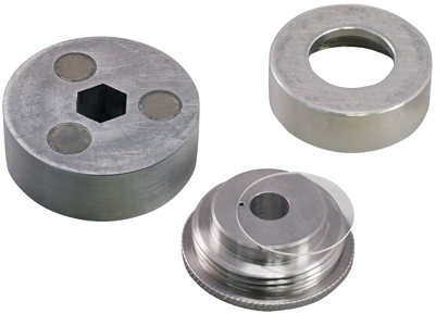
Standard Base, Platen, Ring,
and Sapphire Flat,
for use with Standard Tools
|
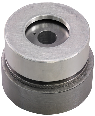
Standard Platen Set
(#83027)
|
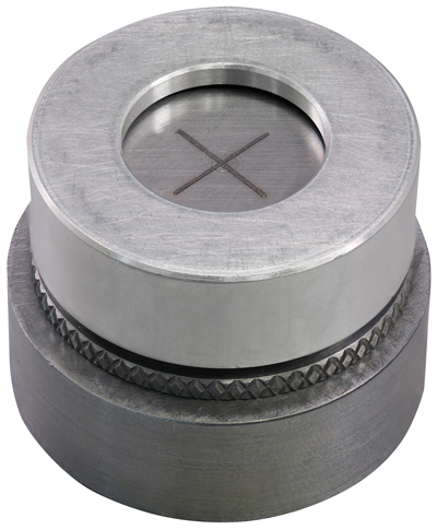
Adjustable Platen Set
(#83032) |
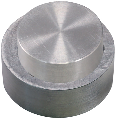
Large Area Platen
with Base (#83007/83040) |
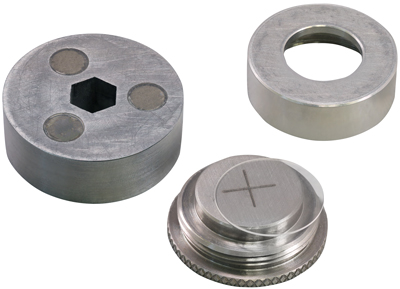
Standard Base, Adjustable Platen,
Ring,
and Sapphire
Flat,
for use with Standard Tools |
|
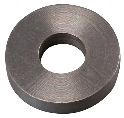
Tool 1i
(#83010) |
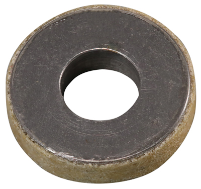
Tool 2iT
(#83014) |
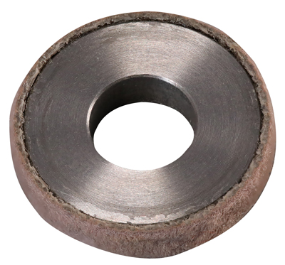
Tool 2iM
(#83013) |
|
(#83011) |
(#83036) |
(#83038) |
(#83037) |
| |
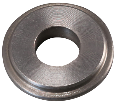
Tool 3i
(#83012) |
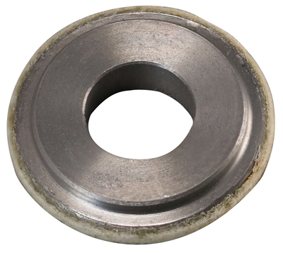
Tool 4iT
(#83016) |
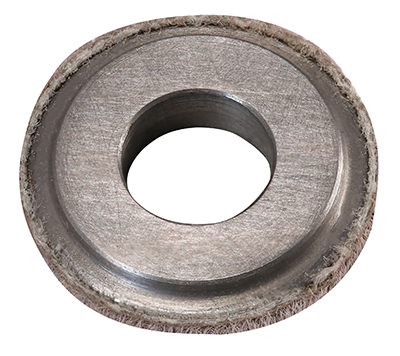
Tool 4iM
(#83015) |
|
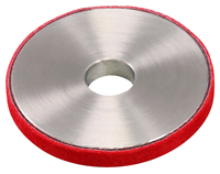
(#83039) |
(#83044) |
(#83045) |
(#83047) |
| |
STANDARD TOOLS |
|
LARGE AREA TOOLS |
PELCO® Dimpler™ & Tools Specifications
| Z Offset |
Accuracy: |
1 micron |
| |
Range: |
2000 microns |
| Z Termination Accuracy |
Tools 1i / 3i: |
<± 1 micron |
| |
Tools 2i / 4i: |
<± 2 microns |
| Tool Force |
Range: |
1 - 200 grams |
| |
|
1 gram steps |
| Balance |
Sensitivity: |
1 gram |
| |
Range: |
50 grams |
| Tool Speed |
100 - 600 RPM |
| Specimen Platen Speed |
10 RPM |
| Tool Shaft |
0.5 micron TIR |
| |
Tools 1i / 3i: |
<± 1 micron TIR |
| |
Tools 2i / 4i: |
<± 2 microns TIR |
| Platen Surface |
< 0.5 micron TIR |
| Dimensions |
Length: |
68.6cm |
| |
Width: |
35.6cm |
| |
Height: |
33cm |
| |
Weight: |
32kg |
| Electrical |
Universal AC Input:100-240VAC, 50/60Hz |
|